
Searching for the most effective means to strengthen concrete deficient in shear? Hilti has you covered.
A background to strengthening
1.0 Introduction
Over the last two decades, the construction industry has come under increasing pressure to reduce its environmental footprint and reuse existing building stock to meet growing socio-economic demands, particularly in urban environments where a sizeable proportion of reinforced concrete buildings and bridges are at the end of their service life and need either refurbishment or demolition. Besides end of service life, a few causes of strengthening existing structures may include:
•A change in use or occupancy,
•An expansion of the building’s footprint,
•Additional floors in dense urban environments that makes expanding horizontally is not viable,
•The introduction of new building codes,
•The presence of errors or other deficiencies in the original construction, and
•The need to address other durability issues caused by known hazards such as fire and earthquake.
The choice to strengthen the existing structure or demolish and rebuild is not always easy and depends on the current condition of the structure, the client’s brief, and the structure’s cultural, historical, and societal importance. If the structural engineer determines that strengthening the entire structure is possible, evidence suggests a 15-70% faster turnaround time (defined as the time between stopping activity in the building or on the bridge and returning it to service) as compared to demolishing and building afresh. Besides saving time, strengthening the structure may achieve a 10-75% reduction in the resource burden through savings in labour and material, directly impacting the structure’s environmental and carbon footprint [1]. A faster return and a lower initial investment are also vital considerations for clients.
2.0 Solutions for strengthening and the selection process
However, these potential savings are strongly predicated upon the structural engineer’s ability to select and the construction industry’s ability to provide and install appropriate strengthening solutions that address identified local and / or global deficiencies. While most strengthening projects will usually incorporate multiple solutions, some are ruled out due to architectural, operational, or geometrical limitations, a lack of knowledge in design and / or execution, unavailability of appropriate equipment, which narrows the list of potential solutions. This selection is further influenced by the advantages and disadvantages accompanying these solutions and are not “silver bullets” miraculously resolving structural deficiencies. Adding another layer of complexity is the potential for flawed implementation of these solutions that may lead to strengthening a particular part of the structure but weakening another, illustrated by the following two examples, one at a local and the other at the global level:
1.Local: thickening the slab with a concrete overlay but ignoring the additional loads on the supporting beams.
2.Global: a high concentration of shear infill walls on one side of the structure increasing the load demand on the other side, achieving the opposite effect.
At a “local” level, deficiencies may include the individual concrete members such as beams, columns, slabs, walls, and foundations lacking sufficient resistance to preclude failure in tension, compression, bending, shear, punching shear, torsion, and other effects caused by new loading demands. Solutions for individual members include, among others:
•Concrete overlays or jackets as seen in Fig.1,
•Post-installed reinforcement,
•Steel jackets,
•Near surface mounted (NSM) or bonded plates,
•Fibre-reinforced polymer (FRP) wraps and strips,
•External post-tensioning.
Fig. 1: An example of concrete overlay / jacketing in columns
Strengthening on a “global” level typically includes addressing issues related to the whole structure, such as seismic, fire, fatigue, and wind by introducing solutions such as:
•Shear infill walls as shown in Fig. 2,
•Steel braces,
•Micro-piles,
•Base-isolation,
•Energy dissipation / damping devices.
Fig. 2: Example of a shear-infill wall between columns
3.0 Strengthening concrete members deficient in shear
Assuming a building previously housing offices now changed to commercial use from a change in ownership, higher footfall will increase load on, say, the floor that must be resisted by all structural components – slabs, beams, columns, and the foundations. Typically, after verification, an engineer may find that the beams lack sufficient resistance in both bending and shear or, in some cases, only shear. Recall that in most design standards, such as Section 6.2 of EN 1992-1-1:2004 [2], the resistance of a concrete member in shear depends on the following six parameters:
1. Concrete strength,
2. Section width, and height
3. Effective depth to the flexural reinforcement from the top of the compression fibre,
4. Length of the support
5. The amount of longitudinal reinforcement
6. The amount of shear (or transverse) reinforcement
Employing a range of potentially available “local”-level solutions to improve one or several of these parameters enhances shear resistance by varying amounts, yet this incurs a trade-off in terms of invasiveness, cost, availability, and other parameters. Some modifications may not be even feasible, such as increasing the concrete strength of an existing beam. Others, such as adding more supports through additional columns to reduce shear demands on one beam may load another beam and will require load transfer to the foundations. Therefore, the potential range of solutions to enhance parameters (1) to (6) may resemble Table 3.1:
Directly increasing the amount of shear reinforcement results in a proportional increase of the shear resistance, and the solutions available presently in the industry are typically minimally invasive and will reduce disruption to other members. Conversely for the concrete shear resistance, the use of other solutions typically results in an under-proportional increase, apart from concrete overlay, which is accompanied by its own trade-offs.
4.0 Post-installed shear reinforcement to increase shear resistance

Fig. 3: Hilti HIT-RE 500 V4, HAS(-U) rods, and filling set used as post-installed shear reinforcement
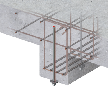
This solution is installed similar to a bonded anchor: i.e., drilling to a fixed embedment depth perpendicular to the concrete surface, thoroughly cleaning the debris from the boreholes, and injecting the mortar and then inserting the rods. Once the mortar cures, the nuts can be torqued up to a maximum specified value.
Note: Unless explicitly considered in design, drilling and cutting through the flexural reinforcement should be avoided wherever possible to prevent further weakening of the structure. If this cannot be avoided, for instance to facilitate drilling in densely reinforced areas, additional measures with the explicit agreement of the Engineer in Charge of design are required to compensate for a loss of flexural reinforcement.
5.0 The new Hilti post-installed shear strengthening solution “HIT-Shear”
The new Hilti HIT-Shear strengthening solution consists of the following components:
Fig. 4: Hilti HIT-RE 500 V4, HAS(-U) rods, and other installation tools
The solution pairs the HIT-RE 500 V4 injection mortar with Hilti HAS series of threaded rods in sizes M12, M16, M20, and M24, each available in carbon- and stainless-steel for indoor or outdoor use. The steel elements are completed by the Hilti Filling Set that consists of a sealing and spherical washer, a nut, and an optional locknut, also available in both carbon- and stainless-steel for each rod diameter.
The versatility of this system leverages a high performing mortar, allowing its use in concrete:
•Of any thickness between 200-2200 mm,
•Of any strength between C20/25 & C50/60,
•Dry or water-saturated concrete, and in waterfilled holes.
•With maximum short- and long-term temperatures of +60°C and +43°C, respectively.
•Members subjected to static, quasi-static, and fatigue loading.
While installation into the concrete member is indeed possible from either side, for instance top-down or bottom-up in a beam or slab, a key feature of the system is the installation of the threaded rods to a specified installation length, 𝑙𝑠𝑤, which is function of the thickness, ℎ, and a residual cover, 𝑐𝑟𝑒𝑠, that prevents, from an installation perspective, concrete spalling at the surface opposite to drilling. The residual cover, as illustrated in Fig. 5, varies according to the rod diameter.
From a design perspective, the fixed installation length ensures the secure anchorage of the rods to replicate the truss model formed by cast-in stirrups.
Fig. 5: Cross-section showing the installation depth and residual cover of the HIT-Shear strengthening solution
6.0 Solution coverage under the German National Approval
In the absence of an existing European Assessment Document (EAD) or a harmonised European standard (hEN), the Hilti HIT-Shear strengthening solution was verified for its fitness for this strengthening application by the Deutsches Insitut für Bautechnik (DIBt) and granted a “general construction technique permit”, or aBG, Z-15.5-383 [4]. This fulfils the national requirement for construction works under the MVV TB (Muster-Verwaltungsvorschrift Technische Baubestimmungen), which serve as a model for the Administrative Provisions – Technical Building Rules that are implemented at a federal level in Germany
7.0 Flexibility in your hands – leverage the power of PROFIS Engineering
Hilti’s cloud-based design software PROFIS Engineering includes a new dedicated module for assessing and strengthening concrete members deficient in shear that assists structural engineers when evaluating the resistance of existing members and strengthening them, thereby ensuring a safer and more efficient workflow. The new PROFIS Engineering Shear Strengthening module enables:
•Selection between beams, columns, slabs, and walls and definition of its material properties & geometry
•Verification of the existing concrete’s resistance to EN 1992-1-1:2004 + National Annex or SIA 262:2017 [5].
•Strengthening with a choice of four reinforcing diameters in carbon- or stainless-steel and a free input the spacing and edge distances.
•Splitting the member into individual zones and leverage the Variable Strut Inclination Method to maximise resistance with the least reinforcement.
•Generation of a comprehensive design report with all verifications, reinforcement detailing, and installation instructions.
8.0 Conclusion
Transforming and reusing older structures can offer many advantages over new build ones, with each structure requiring fulfilment of specific objectives when strengthened. Based on the chosen design philosophy, the structural engineer can address shear deficiencies in linear or planar concrete members through various methods, some less invasive than others. The use of post-installed shear reinforcement, such as Hilti’s solution of HAS(-U) threaded rods with the HIT-RE 500 V4 mortar, is a novel example of a minimally invasive method that can significantly enhance the shear resistance of a structural member.
Suitably assessed and granted a general construction technique permit (aBG) as a system by DIBt, engineers can use a familiar Eurocode 2-based design approach integrated into Hilti’s PROFIS Engineering Suite to arrive at a feasible solution by selecting between the key design parameters of diameter, spacing and the variable inclined strut. With an intuitive interface, the new Shear Strengthening module assists engineers by saving time during the design phase, bringing value to their clients while also contributing to a safer and more resilient built environment.
To start designing, visit https://profisengineering.hilti.com/
References
[1].N. Addy, “Making sustainable refurbishment of existing buildings financially viable”, in Sustainable Retrofitting of Commercial Buildings - Cool Climates, S. Burton, Ed., Abingdon, Routledge, 2015, pp. 57-73.
[2].EN 1992-1-1:2004: “Eurocode 2 - Design of concrete structures - Part 1-1: General rules and rules for buildings”, Brussels: CEN, 2004.
[3].K. S and G. Genesio, “Whitepaper on Shear-friction Applications and Concrete Overlays”, Hilti AG, Liechtenstein, Dec. 2023.
[4].Deutsches Institut für Bautechnik, “Z-15.5-383 - Hilti Querkraft-Verstärkungssystem mit Hilti HIT-RE 500 V4”, DIBt, Berlin, 2024.
[5].SIA, “SIA 262: Concrete Structures,” SIA, Zürich, 2017.